|

| INFORMATION FOR Prospective Students INFORMATION Home PROJECTS Funded QUICK LINKS Optical Devices
|
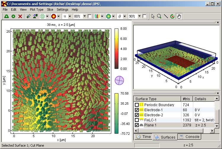
LCview User GuideThis guide is intended to help get you started using the LCview program. The main aim of this program is fast visualisation and exploration of 3D data sets on tetrahedral meshes. It provides visualisation of tensor, vector and scalar fields, and is tailored for the visualisation of liquid crystals. Also supported are 2D data sets and regular meshes. A screen shot of the program is shown below.
The top right hand view is a sketch of the 3D structure. With this view cut planes and iso-surfaces can be selected and moved using the mouse. The left hand view typically visualises the result for the selected cut-plane only. The bottom right hand view has a number of functions. The Time pane is a list of result files in the current directory. Typically each file corresponds to a simulation result at a particular time. This view allows the user to quickly change the result file/time that is being viewed. The Surface pane allows the user to select which surfaces, including those present in the mesh, should be drawn. The Console pane is still under development and currently functions as a simple calculator. Most of the features of the program are available through the following toolbar. Tooltips describe the function of each button when using the program. The function of each button is ellaborated below.
1. Add a new cut plane surface 2. Add a new iso-surface 3. Delete selected surface 4. Plot surface as solid or wireframe 5. Interpolate cut plane data from a triangular mesh to a grid 6. Draw contours or streamlines 7. Background colour map 8. Background colour parameter, e.g. electric potential 9. Background opacity 10. Set the range for the background parameter, global or local to surface 11. Draw directors or the flow 12-15. Same as 7-10 but for the director/flow colour instead of the background Getting StartedIntially when the program loads all the views will appear blank. First of all a result file should be loaded, either using File-Open or by dragging the result file into the program. The top right hand view should now show some axes. Now it's necessary to add some cut planes to visualise the result. To do this Click button 1. A plane should appear on the right hand side. Left click on this plane to select it. Left click - Select surface Right click - Move surface Left double click - Change cut-plane surface normal
This page last modified 11 July, 2007 by r.james |